Configuring a Cisco ICM CTI link
To configure a local CTI link to a Cisco ICM CTI Server, do the following steps:
- Access the administration and configuration options for PegaCALL by clicking .
- Click Add CTI Link and select Cisco ICM/UCCE.
- Configure the CTI link by entering information in the following form:
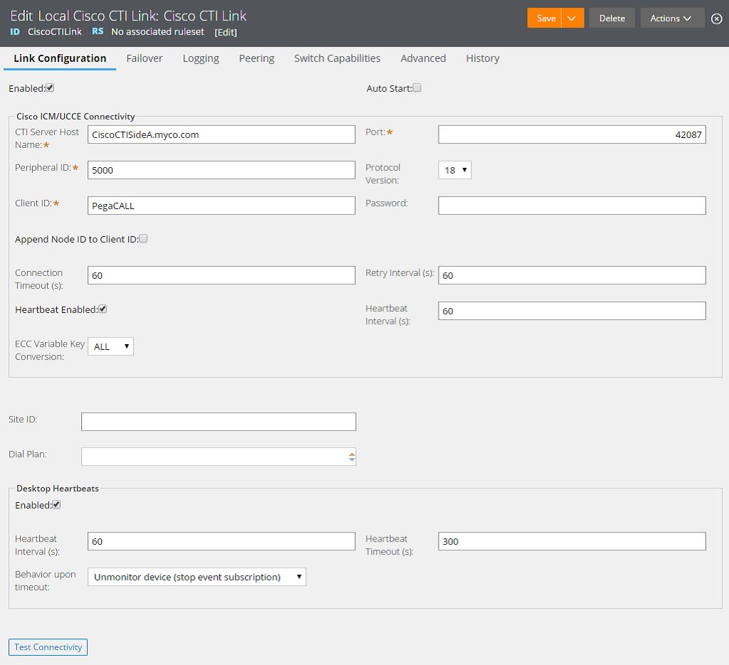
The fields in the form are described below:
Enabled – Select this check box if this CTI link is enabled. PegaCALL attempts to connect to the CTI Server only if the corresponding CTI link is enabled.
- Auto Start – Select this check box if you want to have Pega 7 start the CTI Link Engine when Pega 7 starts. Allowing Pega 7 to autostart a CTI link ensures that the link is ready when a CSR needs to use telephony services.
If Auto Start is not enabled, the first CSR to log in after Pega 7 starts is likely to experience a longer delay before being able to log in.On production systems that have CTI links enabled, select Auto Start. - CTI Server Host Name – Required. Enter the host name or IP address of the CTI Server.
- Port – Required. Enter the port used for SOAP connections to the server.
- Peripheral ID – Required. Enter the ID of the ACD peripheral on Cisco ICM.
- Protocol Version – Select the protocol version from the options provided:
CTI protocol version ICM version 10 7.0 and above 14 8.0 and above 15 8.5 and above 16 9.0 and above 18 10.0 and above - Client ID – Required. Enter the User ID for the CTI user or connection on the CTI Server.
- Password – Enter the password for the CTI user ID on the CTI Server.
- Append Node ID to Client ID – Select this check box to append the Pega 7 node ID to the application name. In a Pega 7 cluster, this enables identification of each Pega 7 node's connection to the Cisco CTI Server.
- Connection Timeout(s) – Enter the time in seconds before a CTI link is considered to be disconnected. The CTI Link Engine waits for this duration after a connection interruption before attempting to connect to a backup CTI Server (if one is configured).
- Retry Interval(s) – Enter the time in seconds between attempts to reconnect to the CTI Server. Set the Retry Interval to a lower value than the Connection Timeout to allow the CTI Link Engine to attempt to reconnect to a CTI Server before attempting to fail over to the backup CTI Server.
- Heartbeat Enabled – Indicate whether to enable heartbeats on the link between the Pega 7 node(s) and the Cisco CTI Server.
- Heartbeat Interval(s) – Enter the time in seconds between heartbeats on the link to the Cisco CTI Server.
- ECC Variable Key Conversion – The CTI Link Engine for Cisco ICM uses a Pega 7 value group to represent ICM’s extended call context (ECC) variables. ECC variable names are mapped to property names. Because Pega 7 property names cannot include periods (.), all periods in ECC variable names received from ICM are mapped to underscore (_) characters in Pega 7 property names. The key conversion setting determines how underscores in the Pega 7 property names are mapped to ECC variable names when variables are sent back to ICM.
You can set this field to All, First, or None.
All – Underscore characters in the property name are mapped to periods in the ECC variable name.
First – Only the first underscore in the property name is mapped to a period.
None – The property name is used as the ECC variable name with no mapping of underscore characters.
- Site ID – Enter a unique identifier for the ACD to which this CTI link connects. If more than one link connects to the same ACD, they all must have the same site ID.
- Dial Plan – Select a dial plan rule to use to place calls with this CTI Link Engine. If no dial plan is selected, dial strings are sent to the PBX/ACD without modification.
- Desktop Heartbeats Enabled – Select to require heartbeats from desktops. If a PegaCALL-enabled desktop stops sending heartbeat messages (such as when a web browser is shut down without properly logging out from CTI), the CTI Link stops monitoring the device (phone or extension) associated with that desktop.
It is recommended that you enable this option to prevent continued monitoring of devices that are not being used and potential problems with subsequent logins. - Desktop Heartbeats Interval(s) – Enter an interval (in seconds) at which heartbeat messages are expected.
- Desktop Heartbeats Timeout(s) – Enter the elapsed time (in seconds) after which, if no heartbeats have been received from a desktop, the CTI link stops monitoring the device that is associated with the desktop. Set this timeout to an interval that is several times greater than the heartbeat interval.
- Desktop Heartbeats Behavior upon timeout – Select the behavior that you want at timeout:
- Unmonitor device (stop event subscription) – Stops the CTI event subscription from the CTI Server for the user's device (extension). PegaCALL no longer monitors the user's extension and does not provide screen pops or UI updates for that extension. The user can no longer control that extension through PegaCALL. The user's agent-state does not change on the ACD.
- Make agent Not-Ready and unmonitor device – In addition to stopping CTI events as described in the option above, PegaCALL attempts to change the user's agent-state on the ACD to "Not-Ready." This option prevents users from receiving customer phone calls from the queue.
- Click Test Connectivity to ensure that your connection is configured correctly.
Configuring the telephony switch type
Before you use the CTI link, configure the type of telephony switch (PBX/ACD) that it is connected to by doing these steps:
- Navigate to the Switch capabilities tab of the CTI Link rule form.
- Click Detect button and verify the type of telephony switch.
- Save the CTI Link rule.