
 Flow form
Editing in Visio — Connectors and flow actions

|
|
Use connectors (sometimes called arrows) to connect a shape element in the flow with the next shape element, to indicate a possible path for the flow execution.
![]() Don't confuse
connectors with Integrator tasks, which support connector
interfaces from a Process Commander system to another system, using
Rule-Connect- rules.
Don't confuse
connectors with Integrator tasks, which support connector
interfaces from a Process Commander system to another system, using
Rule-Connect- rules.
![]() Plan your connectors and
criteria so that at least one is
Plan your connectors and
criteria so that at least one is True no matter what data
values are present. As a good practice, select Else as the
criterion for the connector with the lowest-likelihood.
![]() You can use the notation
param.name in a field to refer to a flow parameter.
You can use the notation
param.name in a field to refer to a flow parameter.
![]() Adding a
connector to the flow — Initial steps
Adding a
connector to the flow — Initial steps
1. Drag the connector shape (![]() ) onto the flow and drop it.
) onto the flow and drop it.
2. Connect the tail end of the arrow to a shape (other than a FlowEnd, Notify, Comment, or Router shape). Connector arrows show as either red or blue. A red end indicates that the "from" (tail) or "to" (head) end of the connector has successfully been connected to a task shape,
3. Connect the head end of the arrow to a shape (other than a Notify, Comment, Ticket or Router shape).
4. If this flow is a screen flow, special rules apply. Continue with Flow Rules — Editing in Visio — Creating and Editing a Screen Flow.
5. When the Connector Properties panel appears, complete the fields that appear.
![]() When you connect the
head end of the connector to a shape that is earlier (above) the tail
end, the connector line changes to a dot-dash pattern (
When you connect the
head end of the connector to a shape that is earlier (above) the tail
end, the connector line changes to a dot-dash pattern (![]() ). This change does not affect the execution of the
flow; the change helps you easily recognize such loops within the
business process. MARIK 3/28/05
). This change does not affect the execution of the
flow; the change helps you easily recognize such loops within the
business process. MARIK 3/28/05
![]() Completing the
Connector Properties panel
Completing the
Connector Properties panel
Field |
Description |
| Application |
|
| Work Type |
|
| Use Case |
|
Three property definitions are possible, depending on where you connect the tail end of the connector:
Complete the Connector Properties panel to identify the connector flow actions available to a user who performs this assignment.
Typically, there are two or more outgoing connectors from a
decision or fork shape, one of which is labeled Else.
Field |
Description |
|
(no label) |
Select
|
| (no label) |
|
| Likelihood |
Enter a percentage between 1 and 100 that indicates how likely you expect that the work object at runtime follows this connector path. If only one path is possible, enter 100. Otherwise, allocate percentages among the multiple paths as appropriate. These can be approximate; you can change them later. When the system lists connector flow actions to the user, they appear sorted by decreasing likelihood values. |
A utility shape can return a literal constant result using the TaskStatus-Set method. C-1375 Similarly, a subflow called from this flow can return a literal constant result to indicate which FlowEnd shape was reached. Complete these fields to have the system test the result returned in these situations to select a connector.
Field |
Description |
|
(no label) |
Select
|
| (no label) |
The value you enter here depends on your selection in the previous field:
|
| Likelihood |
Appears when |
About connector indicators v6.1 proj-179, grp-3558
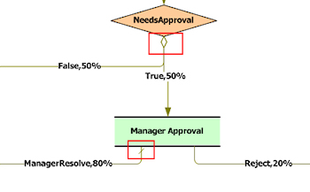
Connectors leaving shapes that have condition or likelihood settings are marked with indicators as follows:
Else setting.When or a Status setting. The Always setting has no indicator.In this example, the True and False connectors leaving the Decision shape have Status settings. The ManagerResolve connector has the highest likelihood value.
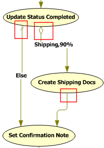
In this example, the connectors leaving the Update Status Completed utility have Else and When conditions. The connector leaving Create Shipping Docs has an Always setting.
![]() Using flow shapes with connectorsv6.1 proj-179
Using flow shapes with connectorsv6.1 proj-179
You can place the flow shapes listed below on a connector. The system automatically re-attaches the existing arrow to the new shape and creates a new arrow that leads to the next shape. Assume you want to place a Decision shape between two Assignment shapes:
When you place the Decision shape on the Submit Order flow action connector, the flow looks like this:
Open the Decision shape and define its properties. Then open the Connector shape leading from it, define it, and add connectors to other shapes as necessary. You can drop the following shapes on a connector:
![]() Connector
Properties — Completing the final fields
Connector
Properties — Completing the final fields
Optional. You can choose to update some property values when the work object follows this connector path in the flow rule. You can also define text to be recorded in work object history.
| Set Properties |
|
| Name |
C-229 |
| Value |
C-229 Optional. Enter a literal value or property reference for the property identified in the Name field.
|
| Audit Note |
Alternatively, enter a brief text phrase, between double quotes.
|
Click Apply when finished.
![]() Refining
likelihood probabilities
Refining
likelihood probabilities
 As a start during initial
development, you can enter approximate likelihood values. Later, after
this flow is used in a production setting, you can use the A
Flow
Analysis button (on the
Design tab) to compare experience with
likelihood values.
As a start during initial
development, you can enter approximate likelihood values. Later, after
this flow is used in a production setting, you can use the A
Flow
Analysis button (on the
Design tab) to compare experience with
likelihood values.
If the actual results vary significantly from the likelihood values,
it can be valuable to understand why. You can update the flow rule
with more accurate likelihood values at any time later; such changes
don't affect the logic or operation of the workflow.
![]() Making a local
action appear first
Making a local
action appear first
At runtime, the system
presents available flow actions in a selection list, with connector
flow actions (sorted by decreasing likelihood) appearing above local
flow actions. In generally, you cannot control the order of the local
flow actions. However, if for one assignment you want to make a local
flow action appear first, add a connector to the flow that loops back
to the assignment, and assign the largest likelihood value to that
connector. HOPPK 7/22/05